Showing posts with label Baseboards. Show all posts

Friday, May 31, 2013

The Completed Baseboards


With a busy schedule, again progress has been slow, but I am glad to say that at last, the two baseboards are complete and have been joined using fixings from a redundant bed from work that was at the end of its life (I manage rented accommodation for students and young professionals).

Back in the kitchen workshop, (only available when my better half is out of the house) and as with the last board, I started by gluing and screwing the end rails and the straight back rail to the baseboard top.


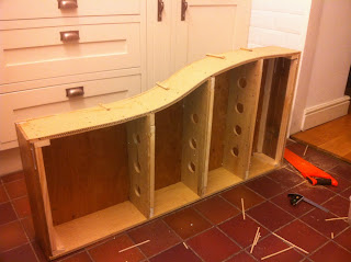
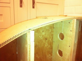
After this I added the cross members and came to the front rail with the compound curve in it. As mentioned before the plan was to use two layers of 6mm bendy MDF laminating them to form the curve.

Tower Street Station Baseboards Under Construction

While cutting the wood I allowed an extra millimetre clearance should any discrepancy's happen, in the end the MDF soaked up the PVA and expanded quite a lot, I managed to hold most of the expansion screwing small batons over the relevant places. Where I was not able to do this the deviance from the original curve has only been 1 or 2mm at most. At leaset all of this will be covered by the final profile board! Next time I will experiment with just one layer of bendy MDF as I don't think the rigidity of the overall structure will be compromised too much.

Tower Street Station Baseboards Under Construction

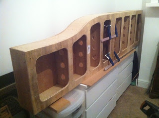
Next the bottom board was glued and screwed in place and again access holes were cut using the jigsaw. The two boards were then taken back up to the hobbies room and clamped together ready to drill the holes for the metal inserts.

Tower Street Station Baseboards Under Construction

M5 socket head bolts to match the inserts were also salvaged from the bed. I managed to get a total of 16 inserts and plenty of screws allowing four bolts per baseboard join to be used. The one thread from each of the pairs of inserts have been drilled out to 6mm so that the bolt can pass through. I did this so that the head of the bolt has a hard surface to bare against rather than just the wood and to prevent he hole from being enlarged by the thread of the bolt. I had designed a version of the pattern makers dowel, which are recommended by John de Frayssinet of County Gate fame, the only difference being they would be large enough to have a hole through the centre to accommodate an M6 or M8 bolt. I will save that design for my next project!

Tower Street Station Baseboard Fixings


Tower Street Station Baseboards and Layout

Next up...

I need to decide which surface to build the track on. Chris Nevard, in his recent article in Model Rail, recommends making the track directly on the top of the baseboard by drawing the track layout on the board, gluing the sleepers down and once dry, soldering the track in place. Another method I have used in conjunction with Alan French at Cardiff MES, is to stick the sleepers to the printed track plan with double sided tape and to solder the track to the sleepers, once assembled pulling away the paper backing and pinning & gluing the whole lot down.

Again, writing the blog and airing various ways of doing things really puts things into perspective and Chris's method starts to seem much more simple and straight forward!!

This is my first layout, and while having helped to make a couple of points at the club, I don't have much experience of copper clad construction, so please do comment if you have any top tips or any other methods of producing the copper clad track work.

Sunday, May 12, 2013

The Kitchen Workshop

It has taken what seems like a lifetime, but at last, one of the baseboards is finished. I might however add some hand holes to aid transportation, but can be done retrospectively. The kitchen has been employed as my makeshift workshop of late as, although the cutting and routing have taken place outside, most of the construction has been done inside to avoid the bad weather!

First off I routed the rebates into the end rails and cut the holes in the cross members.


I then glued and screwed baton to both of the above to enable a good fix to the top & bottom boards and the side rails.

Next I fixed one end rail to both side rails and fixed the top board down to the end rail, matching the end of the board with the rail. I then fixed the other end rail to the top board again making sure the end of the board and the rail were in alignment lengthwise. I then fixed the side rails to the end rails ensuring everything was in alignment.

I could have glued and screwed the end rails and side rails together to start, then added the top board, but I felt it was better to align everything with the top board using that as the datum as I went along to ensure higher accuracy.


After the end rails were in place I fixed the cross members in place and added the bottom board, effectively making it a closed box with no way in...


...Apart from, of course, adding the access holes in the bottom. 


And there you have it! One monocoque baseboard that should stand the test of time and hopefully some rounds on the exhibition circuit!! 

Next up: baseboard two. 

Sunday, April 21, 2013

Sunny Saturday

What better thing to do on a sunny Saturday afternoon when your Mum and Dad are down, than to do some DIY and work on the layout! After botching about widening the door frame of our bedroom and finishing hanging the bathroom door, I managed to have enough time to make a jig and cut the curved boards to size. One of the great things of being the man about the house, is that whatever I am doing with a power tool, it looks like DIY, so when my wife comes out to see how we are doing, it doesn't even enter her head to ask what I'm up to and check that I am still doing the DIY rather than messing about with trains.

First up, I made a template by scribing along the cut of the plot on some spare 12mm ply left over from the side rails, I was going to use some spare laminate but this was too thin and would have made the guide bush on the base of the router sit on the sheet to be cut. I then cut the template using my jigsaw and made sure it was smooth using 80 grit sandpaper.

I then clamped the two sheets at the back making sure they were in line and clamped the jig to the front of the boards 8.5mm from the cut line. The 8.5mm offset is the difference between the diameter of the 30mm guide bush and the 12.7mm (1/2") cutter. Really speaking the measurement should be 8.65mm but I'm not going to split hairs over 0.15mm!

So away I went routing the curve. All was going well until the last pass of the router when I pushed too far and the guide bush went over the end of the template and gave a nice semi circular dent on the edge of my board! Oh well, nothing a bit of filler can't cure later on!


Wednesday, April 17, 2013

Progress at last...

What with the lingering cold weather, a busy family schedule and our rental house needing a complete redecorate, the layout has been on the back burner for a few weeks.

During this time though, I have managed to get the image file across to my friend Andrew Denholm, who has done a splendid job of printing a full size plot of the layout. This will be used as the template on which I will build the track. I mistakenly left in the shaded footprints of two Class 121s and a class 108, which were covering two of the turnouts. I will be need to print out the portions on an A4 sheet and tape them over the offending areas.
The plot arrived on Monday night and was duly unfurled on the floor to check it out, it happens to be millimetre perfect, more perfect then the boards cut by B&Q on they're super duper vertical saw table thingamajig!!

The plan was laid over the top sheet of the left baseboard, taped down and cut using a knife, thus leaving a mark on the board where the curved edge should be cut, the line being overmarked with a pencil. The plan was then taped to the inside face of the bottom sheet of the baseboard and the pencil line repeated.

I have not yet decided how I am going to cut the boards. Ideally I would clamp both boards together and cut them together allowing the both curves to match.

As can be seen in the picture above, I have achieved good results with my domestic (green, as opposed to the industrial blue) Bosch jig saw, which has a good range of blades to choose from, but the one problem I have is that when cutting anything over about 15mm the blade tends to bend a little, resulting in out of square cuts, seen below on the 25mm MDF that makes up my workbench.
                                                                                                                                                     
The alternative would be to make a template using some spare laminate left over from a previous customers job to use with my router, the only difficulty being that the template needs to be cut 8.5mm inside the finished edge to allow for the offset created by the routers guide bush.

The end of our kitchen worktop was created in this way. I spent ages trying to find the centre of the radius on the curved unit and couldn't find one, it then dawned on me that there was no one single radius, but the curve was constantly changing template. (Who designs a kitchen unit without a fixed radius and supplies it without a template so that the kitchen fitter, in this case me, needs to make a bespoke template wasting time in the process??? (Rant Over!)) So I set to creating a template scribed from top of the actual unit, subtracting the 8.5mm clearance needed  for the guide bush and came up with the result below.
As I am typing, the second option seems more and more like the one I need to pursue. It will take more time but it will mean that when trying to mate up the top and bottom boards with the bendy MDF side rail I will know that they are identical and won't have to faff about trying to match two bards that are out of square with one another.

Update to follow...

Saturday, March 30, 2013

Timber!

A bit of progress on the baseboard front yesterday!

Having remembered that in my lockup, I already have sheet of 12mm ply pre cut into 150mm strips for the layout I had started in our previous house, I have updated the plan to make all of the top and bottom sheets, side rails and cross members from 12mm ply. This has the added benefit of enabling two 6mm sheets of bendy MDF to be used on the one side rail that curves on the left hand board These will be laminated together to make which will make a strong section to match the 12mm ply used on the rest of the boards.

Having forgotten to pick up my black and decker workmate on the way home from work before the Easter weekend, the pavement outside the front of the house had to do for my mitre saw, and the kid's Ikea table sufficed for the rest of the jobs.

Next on the list is to route rebates into the oak end rails to accept the side rails and cut some 2x1 for the carcassing.

The curved section of the top and bottom panels of the left hand baseboard will be cut once I receive the full size plot of the layout that a friend has promised to do for me. This plot will also form the basis of the template upon which the track will be built.


Thursday, March 14, 2013

Tower Street Station Track Plan


This is the proposed track plan of the Tower Street Station Layout based on the track plan at Abingdon Station, a typical busy GWR branch line terminus with ample provision of goods yard facilities, which will add to the operational interest of the layout. The plan has been mirrored to suit the location of the layout within our hobbies room and has been compromised in a couple of areas to enable it to fit. The headshunt will remain and will extend onto the traverser to enable longer trains to be worked in the goods yard while keeping the running line free for passenger traffic.

The layout will comprise of two main baseboards, each being 1200mm wide and a traverser fiddle yard also 1200mm wide. The baseboards will be of monocoque construction using 9mm plywood for the tops, bottoms, which will have holes cut out for access, and sides. The side on the left hand baseboard which curves will be formed from bendy MDF while ends of the baseboards will be formed using 20mm thick oak plank left over from flooring our hallways and living room.

All trackwork on the baseboards will be hand made using code 75 bull head rail and copper clad sleepers and ballasted using C+L Finescale 2mm ballast for the running lines and ash ballast for the goods yard and headshunt.

At the moment the plan is to use proprietary kits by Wills, Ratio and Scalescenes for the buildings and accessories including a couple of items from Hornby's Skaledale range and to slowly replace these with scratch built items as my skills develop and time allows.

At the moment an interest in Green Diesel era motive power collides with an enthusiasm of GWR rollingstock and liveries, running sessions at home will not prove a problem, but if the layout ever gets to the exhibition circuit, as is hoped, then investment in GWR motive power will be needed!

The layout will be operated using Bachmann's wireless Dynamis DCC controller and will use a control panel, yet to be designed, for point and signal control. One of the members of Cardiff MES, of which I am a member, has developed and produced a point and signal machine, the signals to be used will be Ratio kit items.

Related Posts Plugin for WordPress, Blogger...